
Harmonic Drive
c. 2018
Precision Engineering
Bethany Chaffin, Ian Sparkman, Keven Wang, Jamie Young
For Stanford’s ME 324, our group became interested in designing a cost-effective strain wave gearing system that improved upon the backlash performance of spur gear drives and approached that of industrial harmonic drives.
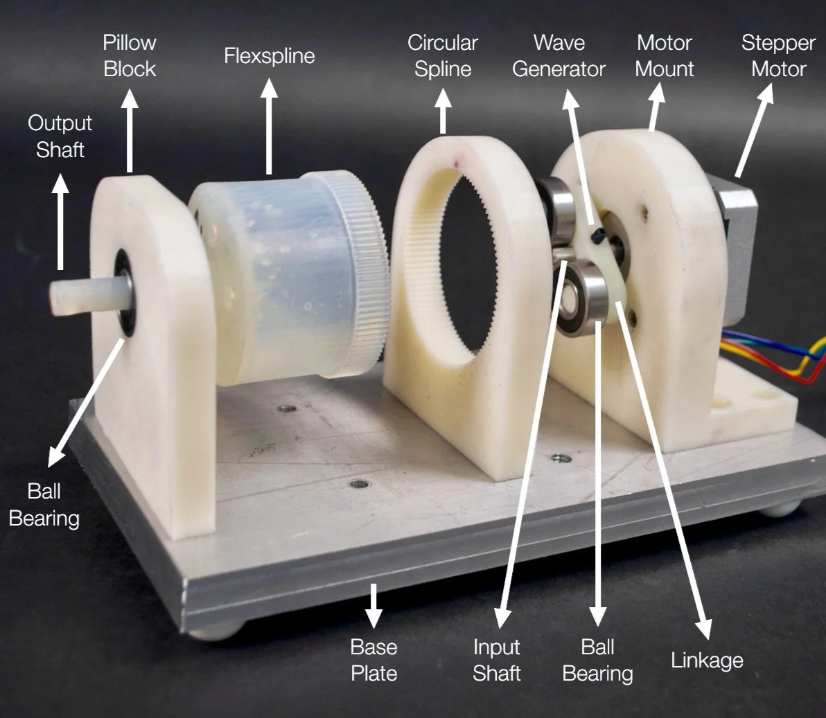
To accomplish this end, we made a number of changes to the traditional harmonic drive design. First, instead of using metal parts which are typically produced through expensive manufacturing processes like EDM, we decided to 3D-print the majority of the system. Second, instead of using an elliptical bearing as the wave generator, we approximated an ellipse by attaching two circular ball bearings to a linkage. Third, we optimized the involute profile of our gear teeth to reduce sensitivity to manufacturing tolerances and ensure proper clearance.
The crux of the design rested in the flexspline, which needed to flex but not deform when driven by the wave generator. Using Durable resin from a Formlabs Form 2 printer, we were able to iterate over wall thickness and print a suitable model.
Ultimately, we built a functional harmonic drive system with a 50:1 gear reduction. To test, we drove the wave generator with a stepper motor controlled by an Arduino Uno that had a resolution of 1.8 degrees +/- 5%. Using a laser attached to the flexspline, we then measured the relative differences in the laser’s position, allowing us to back out rotational accuracy.
After measuring the backlash in both the motor and full system, we determined the isolated harmonic drive backlash to be 2.72 milli-radians on average. Although this exceeded the backlash seen in industrial-grade harmonic drives, it did outperform traditional spur gear drives of equal gear ratios which we estimated to include between 6 - 10 milli-radians of backlash.
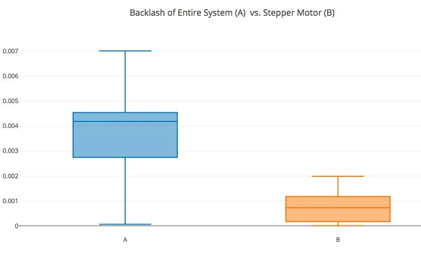
Backlash of entire system (A) vs. Stepper motor (B); dimensions of y-axis in radians


For more information, please see the full Harmonic Drive Report linked below.